- #PARALLEL PORT CNC PINOUT SERIAL#
- #PARALLEL PORT CNC PINOUT DRIVERS#
- #PARALLEL PORT CNC PINOUT DRIVER#
- #PARALLEL PORT CNC PINOUT MANUAL#
- #PARALLEL PORT CNC PINOUT SOFTWARE#
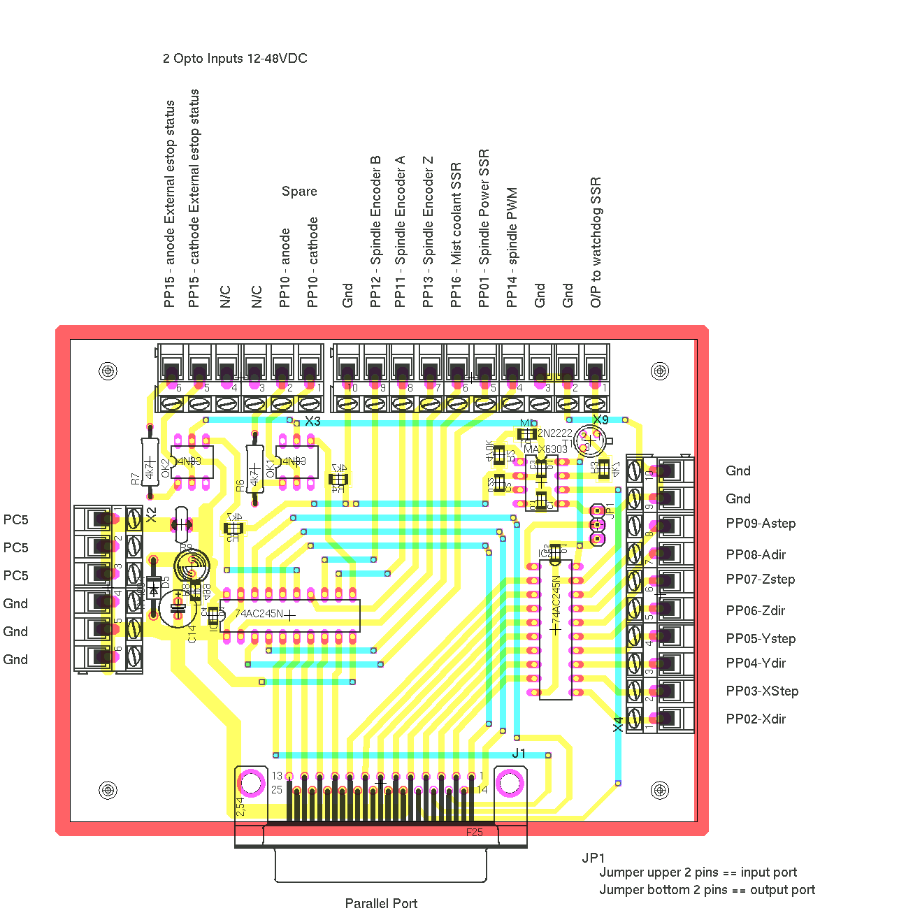
So, I figured, the best way to test this would be to make a utility that could read and set the pins on a parallel port to test this out. This really irked me and I wanted to see if it was really the case. It looked like from the pinout table that there was a typo where two rows were transposed.
#PARALLEL PORT CNC PINOUT MANUAL#
The pinout for the parallel port header from the manual was slightly different from the adapters when I tested it with a continuity meter. I was able to find some adapters (from an old Pentium 133 machine) that connected to these headers and hoped for the best. Luckily, in the motherboard manual was a page dedicated to the pinout of the headers.
#PARALLEL PORT CNC PINOUT SERIAL#
This was a massive problem since all my microcontroller programmers and IO is done through parallel and serial ports. The motherboard (Gigabyte EP45-UD3L) had headers to which you could connect parallel and serial adapters, but there was no parallel or serial connectors on the motherboard. I built myself a new computer recently and it eventually dawned on me that there was no parallel port on it! Well, not quite. Read documentation for C++ parallel port class Motivation With this new knowledge, you will be armed with the necessary experience and information to troubleshoot any possible problems that may exist.Yi Yao > Projects > Parallel Port Control for Linuxĭownload C++ parallel port class and diagnostic utility
#PARALLEL PORT CNC PINOUT DRIVER#
A single motor has been tested and turns, so we know that the breakout board is working and the driver and motor function properly, so the remaining motors can be connected confidently.
#PARALLEL PORT CNC PINOUT DRIVERS#
All of the drivers are connected to the breakout board and are getting 36 volts of power from the main power supply.
#PARALLEL PORT CNC PINOUT SOFTWARE#
The software is correctly setup and the parallel port is showing the correct signals. The breakout board is connected and powered by the 5 volt supply. Two power supplies are connected supplying 36 volts for the motors and 5 volts to condition the signals. In summary, all of the electronics have been connected. The power wires, can disrupt (or influence) the signal voltage, pushing it outside of its comfort zone. Why is this important? Signals have a somewhat narrow range of voltage within which they are allowed.

It is important to think through the placement of the drivers so the wires are short and the power wires are far away from the signal wires. So, with the first driver and motor turning and making noise, it's time to connect all of the drivers. In general, I recommend lead screw be set for 1/4 microstepping and timing belt, roller chain or rack and pinion mechanics be set to 1/16 microstepping to allow more resolution. To make sure that we are delivering the proper signals strength and resolution to the motors, the dip switches are set. The motor is connected in parallel to the terminals labeled A+, A-, B+, B- on the driver. This will allow the motor to have the most torque at a high speed.

For the power supply that I am using, wiring the motor in parallel is the best option. The torque and the power requirements that enable this torque. On the datasheet, there are a few numbers that are important to understand. The datasheet for the motor illustrates three different ways that the motor can be connected to the driver: unipolar, bipolar serial and bipolar parallel.


The stepping motor must be connected in a special way. This power is distributed to the individual coils of the motor in special sequences that relate to moving in a particular direction and at a single step. To get power to the motors, the 36 volt power from the main power supply is connected to the driver. Go to the new parallel breakout board to get more information and the wiring diagram. The new parallel breakout board appears a bit different, but the process of wiring and testing is the same. The wiring of the parallel breakout board from the output terminals to the driver digital pulse (step pulse) and direction lines are explained. I thoroughly explain the wiring of the power supply, an optional 5v power supply to provide a 5v digital supply to the parallel breakout board. The steps per inch for many forms of mechanical option are also explained in depth. I have put together another set of wiring instructions that demonstrate a methodology that begins with a simple and straightforward wiring of only one driver and motor and follows with the remaining drivers while testing throughout. Overwhelmingly, I have noticed the electronics pose the most difficulty with new users. Most of the tutorials on this site are created in response to the difficulties I see users having with machines mechanics, structural dimensions and the electronics that drive their CNC machines. This tutorial will make you an expert in wiring CNC electronics using a parallel breakout board and standard stepping motors and stepping motor drivers.


 0 kommentar(er)
